MST 802.1s
- Was introduced as response to pvst +. PVST generates a spanning-tree for each vlan this is mainly used so you can load balance so say set vlan 10 rootbridge as switch A so it is forwarding path through switch A and vlan 11 root bridge is set as switch B and it has a differtent forwarding path through switch B. So you can plan your network to load balance the traffic through the links.
- Issue is too many spanning-tree instance 1 per vlan if you have alot of vlan this could be significant on your processor . Most layer 2 networks have limited number of paths . So per singular vlan load balancing tends not to be required
- MST allows us to group certain vlans into stp instance and group another set vlans into another stp instance. Essentially lowering the total number of stp instances while still maintaining load balancing flexibilty
- MST is backward compatiable with 802.1d and compatiable with 802.1w it does this by assigning the 802.1d in seperate region and running in compatiablity mode
- It uses 802.1w stp in it stp instances so does not have to run in compatiablity mode for this just treat as seperate region
- To be in the same region a switch must have same region name (32 characheter name) revision number and vlan to instance mapping
- Each region can support up to 65 spanning-tree instances
- if a vlan is not asssigned manually by admin to an instance it is put into the default instance 0
- In a region instance 0 is resevered for IST. IST is the only instance that propgates bpdus. This is for efficency. In order to propgate bpdus for other instances we piggyback the instance 0 bpdus with encaspulated mrecords for each instance bpdus
- All other instances share common timers with instance 0 but may have different parameters root bridge id,port cost etc
- All switches in the regions to outside regions appear as 1 switch
- In our region we need to elect a regional root CIST Regional Root to communicate on behalf of all switches in the region
- For the common spanning-tree among all regions we need to elect a CIST Root.
- CIST root is elected based on priority and lowest mac. CIST regional is based on lowest cost to CIST root
- CIST regional root will elect one of it ports the root port and block all other ports out of the region
- non regional roots boundary switches either block there boundary ports or have them designated based on typical spanning-tree designated port election
- The end result is we have spanning-tree instances running within the region and then 1 common spanning-tree running between all regions.
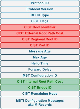
.Below is an MSTP bpdu.
spanning-tree mode mst - set mode to mst
spanning-tree mst configuration- enter mst config mode
name 'regionname' - set mst region name
revision 'revisionno' - set mst revision number
instance 'instanceid' vlan 'vlan range' - specify instance id and vlan range
spanning-tree vlan 'vlan id' root primary/secondary - set switch as root for vlan this a macro that checks current vlan root and decrements lower than it. It does not take account future switches coming on with lower priority. This commands works for 802.1d and 802.1w also.
Rapid Spanning Tree
- came about as the delay of convergence for spanning-tree 802.1d was too slow for real time networks (taking 45secs to 1minute) to converge. With the advent of real time traffic like voip video over ip and delay sensitive traffic like citrix a faster solution was required.
- The biggest difference is it is not timer based spanning-tree 802.1d used cautionary timers like max age + forward delay of listening as a way of being sure that change had occured and to start to reconverge the spanning-tree this lead to slow down on spanning-tree convergence.
- Switches in rspt generate bpdus to other neighboring switches as way of communcating rather than just the root bridge generating bpdu which was the case 802.1d
- RSTP use a synch process neighboring switches can agree very quickly on the status a design of the spanning-tree during initial setup and during spanning-tree changes making the convergence extremely quick
- In order for this synch process to work out the port the switche need to know there ports are only connected to 1 neighboring switch so the ports must be full duplex and p2p
- we have cut down state of discarding/learning and forwarding
- we have more port roles with root designated edge and backup
- root remains the same as always lowest cost to root bridge
- alternative is the inbuilding of uplink fast it provides an alternate port to the root brige in case of root port failure
- edge port inbuilding of port fast it for ports connecting to non switching devices configured the same as port fast
- a backup port provides a back to designated port for the segment it is on.
- When a switch detects a change it starts a tc timer (twice the hello time) + flushes it cam table while this timer is on it generates all bpdus out with tcn set bpdus. On reciept of tcn marked bpdu neighboring switches do the same so propgates through the spanning-tree very quickly.
- RSTP is backward compatiable with 802.1d. When a switch recieves a 802.1 d bpdu it will wait twice the hello time and then fall back to compatablilty mode with 802.1d.
- if you do sh spanning-tree vlan "vlanid" if you see p2pedge your connected to rstp switch if you see p2peer(stp) your connected to legacy spt device

Commands
config() spanning-tree mode rapid-pvst
FLEX LINKS
- Define a backup link for a interface like an alternative for small scale enviorments to spanning-tree
- Use thee mmu(mac address move) when switching to backup interface to spoof updates for all sources out new port inorder to get upstream switches to update there cam tables without causing flooding.
- When you enable this backup link you disable stp on the primary and backup link
- You have to enable mmu on all switches.
Configuration
int fa0/13
switchport backup interface fa0/17 mmu primary vlan 1
mmu is mac address move feature and the vlan is the vlan that the mmu data will be sent out
you also have to enable the mac address table move on all switches
mac-address-trable move update (recieve/transmit) so transmit on the switch with the backup interface and recived on the other switches
sh mac address-table move update
sh interface switchport backup
switchport backup interface fa0/17 premption mode force/bandwidth
also you may want to enable preemtion if the case your primary link comes backup to do
this in interface modeforce will always return to the primary specfied link bandwidth will preempt in the case that one link gets increase bandwidth
switchport backup interface fa0/17 premption delay 'in sec' to say how long it should wait to preempt
No comments:
Post a Comment