Tuesday, December 6, 2011

Frame Relay Back to Back + End to End KeepAlive EEK


FRAME RELAY BACK TO BACK

  • 2 routers directly connected over the serial link running encap frame relay with no fr switch in between
  • As there is no switch advertising dlci numbers the the listing will keep appearing as disabled
  • The way to get around this is to disable the lmi probe
Commands

int s0/1
encap frame-relay
no keep-alive
frame-relay interface ( if you want to discover the other side via inverse arp)
or
frame-relay map ip 10.1.1.1 'dlci no'

note the dlci number will be the same both side as there is only the one dlci.
The config is the exact both side apart from ip.


EEK

  • EEK (end to end keepalives)It is an add on that checks the status of link end to end so from dte to dte not just  to dce on the frame-relay switch.
  • This feature is supported natively in LMi but is not supported in situation for example in non standard frame-relay setups for example your frame-relay is being encapsulated over the service provider. 
  • LMI also runs over there control specified signalling channels while EEK runs on the dlci
  • Encapsulation of keepalive packets is proprietary; therefore, the feature is available only on Cisco devices 

 MODES
In bidirectional mode, both the send side and receive side are enabled, and the device sends out and waits for replies to keepalive requests, and also waits for and replies to keepalive requests.

In request mode, only the send side is enabled, and the device sends out and waits for replies to its keepalive requests.

In reply mode, only the receive side is enabled, and the device waits for and replies to keepalive requests.

In passive-reply mode, the device only responds to keepalive requests, but does not set any timers or keep track of any events.


COMMANDS

 map-class frame-relay EEK
 frame-relay end-to-end keepalive mode request
!
to apply you can use the
interface Serial0/0/0
 ip address 10.229.254.1 255.255.255.0
 encapsulation frame-relay
 no fair-queue
 frame-relay class EEK
end
frame-relay class command this will apply to the interface and to all subinterface if
you only want it on a particular dlci
go to the dlci and enter the command
frame-relay class 'name'
this will apply it just to the dlci.

now on the sh frame-relay pvc you see the addess eek up. The monitor is on the dlci

DLCI = 405, DLCI USAGE = LOCAL, PVC STATUS = ACTIVE (EEK UP), INTERFACE = Serial0/0/0
  input pkts 1             output pkts 2            in bytes 34
  out bytes 41             dropped pkts 0           in pkts dropped 0
  out pkts dropped 0                out bytes dropped 0
  in FECN pkts 0           in BECN pkts 0           out FECN pkts 0
  out BECN pkts 0          in DE pkts 0             out DE pkts 0
  out bcast pkts 1         out bcast bytes 34
  5 minute input rate 0 bits/sec, 0 packets/sec
  5 minute output rate 0 bits/sec, 0 packets/sec
  pvc create time 00:00:04, last time pvc status changed 00:00:04

Monday, December 5, 2011

FRAME RELAY LAB MAIN INT,MULTI SUB INT,P2P SUBINT

Today I looked at the different frame relay configuration. I just done this in a lab
with 3 of the router r1,r4 and r5
My findings below

Main Interface-Main Interface full mesh connectivity


So first lab was main interfaces on all configured and inverse arp is on + topology is
in a full mesh
so
r1 local dlci 105 - r5 local dlci 501
r1 local dlci 104 - r4  local dlci 401
r4 local dlci 405 - r5 local dlci 504

The first thing i noticed when you enable encap frame relay on  the router interfaces
+ give it an ip. Inverse arp is going kick in and it will send out inverse arp reques
on all the dlci lmi has picked up. As the lab is in full mesh you may start recieving
replies from other routers you do not want in the scope. So i had r3 configured from
last night and it picked up that and created a map entry for it.
so on r1 i have configured the following
interface Serial0/0
 ip address 10.229.254.1 255.255.255.0
 encapsulation frame-relay
 frame-relay lmi-type cisco

This config will be the same on each of the routers apart from ip address so r1
10.229.254.1 r2 10.229.254.1 r5 10.229.254.3

r1#sh frame-relay map
Serial0/0 (up): ip 12.12.12.12 dlci 103(0x67,0x1870), dynamic,
              broadcast,, status defined, active
Serial0/0 (up): ip 10.229.254.2 dlci 104(0x68,0x1880), dynamic,
              broadcast,, status defined, active
Serial0/0 (up): ip 10.229.254.3 dlci 105(0x69,0x1890), dynamic,
              broadcast,
              CISCO, status defined, active
Notice it has pick up 12.12.12.12 ?? this was configured on r3 which i do not want in
the topology.


As this is potential issue in the ccie lab which is full meshed. To resolve this we
can do the following.
You can manually assign the rogue dlci to a sub interface
r1#sh run int s0/0.1
!interface Serial0/0.1 multipoint
 frame-relay interface-dlci 103
end
this will run iverse arp as there has been no ip address assigned
r1#sh frame-relay map
Serial0/0 (up): ip 10.229.254.2 dlci 104(0x68,0x1880), dynamic,
              broadcast,, status defined, active
Serial0/0 (up): ip 10.229.254.3 dlci 105(0x69,0x1890), dynamic,
              broadcast,
              CISCO, status defined, active
I only see the 2 required subnets that i want
I have full connectivity

r1#ping 10.229.254.2
Type escape sequence to abort.
Sending 5, 100-byte ICMP Echos to 10.229.254.2, timeout is 2 seconds:
!!!!!
Success rate is 100 percent (5/5), round-trip min/avg/max = 64/65/68 ms
r1#ping 10.229.254.3
Type escape sequence to abort.
Sending 5, 100-byte ICMP Echos to 10.229.254.3, timeout is 2 seconds:
!!!!!
Success rate is 100 percent (5/5), round-trip min/avg/max = 64/65/68 ms
r1#

Main-interface to main-interface partial mesh

so in this i will do it as if r1 is the hub and r4 + 5 are spokes. R4 + R5 do not have
connectivity to each other

r1 local dlci 105 - r5 local dlci 501
r1 local dlci 104 - r4  local dlci 401

At the moment it is still in full connectivity
r5(config-subif)#do sh frame-relay map
Serial0/0/0 (up): ip 10.229.254.1 dlci 501(0x1F5,0x7C50), dynamic,
              broadcast,
              CISCO, status defined, active
Serial0/0/0 (up): ip 12.12.12.12 dlci 503(0x1F7,0x7C70), dynamic,
              broadcast,, status defined, active
Serial0/0/0 (up): ip 10.229.254.2 dlci 504(0x1F8,0x7C80), dynamic,
              broadcast,,
In order to get rid of the dlci between r5 - r4
nterface Serial0/0/0.1 multipoint
 frame-relay interface-dlci 503
 frame-relay interface-dlci 504
end
i have assigned the dlci 503 to the subinterface multipoint turning of inverse arp on
that sub interface i also done 504 to get rid of the 12.12.12.12 network

r5#sh frame-relay map
Serial0/0/0 (up): ip 10.229.254.1 dlci 501(0x1F5,0x7C50), dynamic,
              broadcast,
              CISCO, status defined, active
so i only have one frame-relay map learnt via inverse arp to r1
I need to repeat the above on r4
Ok so from r4 i can ping 10.229.254.1 r1 but not 10.229.254.3 r5

r4#ping 10.229.254.1
Type escape sequence to abort.
Sending 5, 100-byte ICMP Echos to 10.229.254.1, timeout is 2 seconds:
!!!!!
Success rate is 100 percent (5/5), round-trip min/avg/max = 64/65/68 ms
r4#ping 10.229.254.3
Type escape sequence to abort.
Sending 5, 100-byte ICMP Echos to 10.229.254.3, timeout is 2 seconds:
.....
Success rate is 0 percent (0/5)
r4#
This is down to not have a frame-relay map statement for it
ok i have added a frame-relay map statement on r4. One thing to note when you add a
frame-relay map it will turn off inverse arp. So you will need to manually add one for
r1 also

r1 can ping but r5 is still not responding i need to add frame-relay map on r5 also

so success both ways after manually mapping
Sending 5, 100-byte ICMP Echos to 10.229.254.1, timeout is 2 seconds:
!!!!!
Success rate is 100 percent (5/5), round-trip min/avg/max = 64/65/68 ms
r5#ping 10.229.254.2
Type escape sequence to abort.
Sending 5, 100-byte ICMP Echos to 10.229.254.2, timeout is 2 seconds:
!!!!!
Success rate is 100 percent (5/5), round-trip min/avg/max = 128/131/140 ms
r5#

OK i will go onto the next one a quick way to reset your config on each interface on
r1 r3 r5 do an encap ppp and then back to encap frame-relay reset the interface to
base config with ip set. I am going turn off r3 to stop recieving the 12.12.12.12
network

Multipoint sub interface on r1, p2p sub int on r4 and main interface on r5 in partial
mesh

r1 local dlci 105 - r5 local dlci 501
r1 local dlci 104 - r4  local dlci 401

so i will start r1 everything is in it main interface config

r1
-----
interface Serial0/0
 no ip address
 encapsulation frame-relay
!
interface Serial0/0.1 multipoint
 ip address 10.229.254.1 255.255.255.0

r1#sh frame-relay map
r1#
so after enabling multipoint i have lost all frame-relay mappings

i need to specify what dlci are on the interface to be used
interface Serial0/0
 no ip address
 encapsulation frame-relay
!
interface Serial0/0.1 multipoint
 ip address 10.229.254.1 255.255.255.0
 frame-relay interface-dlci 104
 frame-relay interface-dlci 105

it now has both map entries learnt through inverse arp
r1#sh frame-relay map
Serial0/0.1 (up): ip 10.229.254.2 dlci 104(0x68,0x1880), dynamic,
              broadcast,, status defined, active
Serial0/0.1 (up): ip 10.229.254.3 dlci 105(0x69,0x1890), dynamic,
              broadcast,, status defined, active
and both are pinging

r5
-----
interface Serial0/0/0
 no ip address
 encapsulation frame-relay
 no fair-queue
!
interface Serial0/0/0.1 point-to-point
 ip address 10.229.254.3 255.255.255.0
r5#sh frame-relay map
r5#
no frame-relay map i will specify the dlci it is to use

interface Serial0/0/0.1 point-to-point
 ip address 10.229.254.3 255.255.255.0
 frame-relay interface-dlci 501
!

r5#sh frame-relay map
Serial0/0/0.1 (up): point-to-point dlci, dlci 501(0x1F5,0x7C50), broadcast
          status defined, active
r5#
notice it has no ip address mapped it just says point to point dlci 501. This basically because it is point to point it knows it only has one dlci so the way the router looks at it is that all traffic should forward out there


r5#ping 10.229.254.1
Type escape sequence to abort.
Sending 5, 100-byte ICMP Echos to 10.229.254.1, timeout is 2 seconds:
!!!!!
Success rate is 100 percent (5/5), round-trip min/avg/max = 64/65/68 ms
r5#
I can ping r1 but not r4 .

r4
---
On r4 i put
debug ip packet
the output as follows when i try ping from r5. R5 is reaching it but it is unable to reply
*Dec  5 21:27:44.531: IP: tableid=0, s=10.229.254.3 (Serial0/0/0), d=10.229.254.2 (Serial0/0/0), routed via RIB
*Dec  5 21:27:44.531: IP: s=10.229.254.3 (Serial0/0/0), d=10.229.254.2 (Serial0/0/0), len 100, rcvd 3
*Dec  5 21:27:44.531: IP: tableid=0, s=10.229.254.2 (local), d=10.229.254.3 (Serial0/0/0), routed via RIB
*Dec  5 21:27:44.531: IP: s=10.229.254.2 (local), d=10.229.254.3 (Serial0/0/0), len 100, sending
*Dec  5 21:27:44.531: IP: s=10.229.254.2 (local), d=10.229.254.3 (Serial0/0/0), len 100, encapsulation failed
Encapsulation failed

it has no defined map for 10.229.254.3
r4#sh frame-relay map
Serial0/0/0 (up): ip 10.229.254.1 dlci 401(0x191,0x6410), dynamic,
              broadcast,, status defined, active

By adding a map statement for both .3 and .1 the topology is complete i can ping from everywhere
interface Serial0/0/0
 ip address 10.229.254.2 255.255.255.0
 encapsulation frame-relay
 no fair-queue
 frame-relay map ip 10.229.254.3 401
 frame-relay map ip 10.229.254.1 401

One of the things to watch for
frame-relay map ip  when you are using the same dlci for multiple destinations like in the above 401
if you require support for broadcast or multicast you need to specify the broacast keyword after the map statement. This only has to specfied once for protocol + dlci
so for example in the above
 frame-relay map ip 10.229.254.3 401 broadcast
 frame-relay map ip 10.229.254.1 401
you would only specify it once as if you specify it again it treats it as another broadcast so pseudo broadcast for every dlci with the broacast even if they are the same so you are generating aload of traffic for no reason on the dlci.
Note if you were using ipv6 with the same dlci as it is a different protocol you need to specify it once for that also

Sunday, December 4, 2011

Frame Relay Switch Install

Frame-Relay Switch Install

Configuration of frame relay switch on cisco router  for labs is fairly straight forward

I am using a cisco 2610 with serial 8 a/s card. I have my dce of my serial cables
connected to the cisco 2610 fr switch and the dte connected to the relevant routers
The first thing that needs to be done in global config mode on the fr switch is to
enable frame-relay switching
router(config)#frame-relay switching
then you go to your relevant serial interface depending on the device you are
connecting so I am doing router 6 which connects to s1/4 on my frame relay switch
this is going to communicate to router 5 on interface serial 1/5
int s1/4
encap frame-relay
clock rate 56000
frame-relay intf-type dce
no frame inverse
frame-relay route 122 interface serial 1/5 221

int s1/5
encap frame-relay
clock rate 56000
frame-relay intf-type dce
no frame inverse
frame-relay route 221 interface serial 1/4 122

As your dce you need to put clocking
The frame-relay route command breaks down as follow
frame-relay route 221 (r6 dlci) interface serial 1/4 (interface to outgoing dlci so r5
connected interface) 221 ( r5 dlci)

For the ine config i have the following physical connections for the routers to the frame relay switch
                        
r3 s1/0 is connected to s1/6
r3 s1/1 is connected to s1/7
r2 s0/0 is connected to s1/2
r1 s0/0 is connected to s1/0
r4 s0/0 is connected to s1/3
r5 s0/0 is connected to s1/5
r6 s0/0 is connected to s1/4
The config for the switch is below in full
fr#sh run
Building configuration...
Current configuration : 2982 bytes
!
version 12.3
service timestamps debug datetime msec
service timestamps log datetime msec
no service password-encryption
!
hostname fr
!
boot-start-marker
boot-end-marker
!
!
no aaa new-model
ip subnet-zero
ip cef
!
!
!
frame-relay switching
!
!
!
!
interface Ethernet0/0
 no ip address
 shutdown
 half-duplex
!
interface Serial1/0
 no ip address
 encapsulation frame-relay
 clock rate 56000
 no frame-relay inverse-arp
 frame-relay intf-type dce
 frame-relay route 102 interface Serial1/2 201
 frame-relay route 103 interface Serial1/6 301
 frame-relay route 104 interface Serial1/3 401
 frame-relay route 105 interface Serial1/5 501
 frame-relay route 113 interface Serial1/7 311
!
interface Serial1/1
 no ip address
 shutdown
!
interface Serial1/2
 no ip address
 encapsulation frame-relay
 clock rate 56000
 frame-relay intf-type dce
 frame-relay route 202 interface Serial1/0 102
 frame-relay route 203 interface Serial1/6 302
 frame-relay route 204 interface Serial1/3 402
 frame-relay route 205 interface Serial1/5 502
 frame-relay route 213 interface Serial1/7 312
!
interface Serial1/3
 no ip address
 encapsulation frame-relay
 shutdown
 clock rate 56000
 no frame-relay inverse-arp
 frame-relay intf-type dce
 frame-relay route 401 interface Serial1/0 104
 frame-relay route 402 interface Serial1/2 204
 frame-relay route 403 interface Serial1/6 304
 frame-relay route 405 interface Serial1/5 504
 frame-relay route 413 interface Serial1/7 314
!
interface Serial1/4
 no ip address
 encapsulation frame-relay
 clock rate 56000
 no frame-relay inverse-arp
 frame-relay intf-type dce
 frame-relay route 51 interface Serial1/1 51
 frame-relay route 100 interface Serial1/1 100
 frame-relay route 101 interface Serial1/1 101
 frame-relay route 201 interface Serial1/1 201
 frame-relay route 301 interface Serial1/1 301
 frame-relay route 401 interface Serial1/1 401
!
interface Serial1/5
 no ip address
 encapsulation frame-relay
 clock rate 56000
 no frame-relay inverse-arp
 frame-relay intf-type dce
 frame-relay route 501 interface Serial1/0 105
 frame-relay route 502 interface Serial1/2 205
 frame-relay route 503 interface Serial1/6 305
 frame-relay route 504 interface Serial1/3 405
 frame-relay route 513 interface Serial1/7 315
!
interface Serial1/6
 no ip address
 encapsulation frame-relay
 clock rate 56000
 no frame-relay inverse-arp
 frame-relay intf-type dce
 frame-relay route 301 interface Serial1/0 103
 frame-relay route 302 interface Serial1/2 203
 frame-relay route 304 interface Serial1/3 403
 frame-relay route 305 interface Serial1/5 503
!
interface Serial1/7
 no ip address
 encapsulation frame-relay
 clock rate 56000
 no frame-relay inverse-arp
 frame-relay intf-type dce
 frame-relay route 311 interface Serial1/0 113
 frame-relay route 312 interface Serial1/2 213
 frame-relay route 314 interface Serial1/3 413
 frame-relay route 315 interface Serial1/5 513
!
ip http server
ip classless
!
!
!
line con 0
line aux 0
line vty 0 4
 login
!
!
end

Frame Relay Basic Concepts Overview

FRAME RELAY CONCEPTS
  • Frame relay puts data in variable-size units called "frames" and leaves any necessary error-correction (such as re-transmission of data) up to the end-points. This speeds up overall data transmission. Alot of the Wan technologies like T1 for example are stuck to fixed frame size + di extensive error checking.So this use of variable size in the wan made frame relay attractive
  • 2 types of frame-relay encapsulation cisco or ietf can be enabled on per vc basis
  • Lmi is the signaling protocol between the dte router and dce which is the fr switch
  • lmi types supported are cisco (dlci 1023) ansi annex d (dlci 0) and q933a (dlci0)
  • from the output of show frame-relay pvc status  if you see active-connection is good between router + fr switch inactive- dlci number is incorrect + problem with connection deleted-dcli number is incorrect it is not what the sp or fr switch is advertising
  • When encap frame relay is issued the router will learn all dlci associated with that interface. Then when ip is configured inverse arp request will be sent on these dlci other configured sides will replay
  • Inverse arp is a dynamic way of mapping layer 3 address to layer 2 dlci
  • if you statically configure a frame-relay mapping it will disable inverse arp from sending but not replying
  • if you statically configuring do not forget 'broadcast' to enable pseudo broadcast accross the line
  • if you disable frame-relay inverse arp on the main interface it does not disable it on the sub interfaces
  • inverse arp is disabled by default on frame-relay multipoint interfaces
  • static frame-realy mapping override dynamic inverse arp mappings
  • by default split horizon is off on multipoint main interface but not on sub interfaces 
  • frame relay can have issue with autoinstall if you see a mapping for 0.0.0.0  in output for sh frame-relay map command save the config + restart.
  • If we are in a partial mesh scenerio using the multipoint interface or multipoint sub interface we need to manual map ip for each spoke address we will learn the hub ip address but not the spokes ip address as we have no direct layer 2 connectivity
  • P2P does not need manually mapping as presumed all traffic goes out configured dlci as it is the only one


NBMA Interface Types Requirement for Layer 2 to Layer 3 resolution

Multipoint Interfaces

  • These type interface can be assigned + terminate multiple layer 2 ciruits. Effictevly the interface has multiple layer 2 addresses.
  • These interfaces require layer 2 to layer 3 resolution.
  • An example in frame relay would be having multiple dlci assigned to frame relay main interface
frame-relay map "protocol"  "ip address" dlci 'dlcino' - for static mappings

Point-to-Point

  • Can terminate only 1 layer 2 circuit. Only one possible layer 2 address. So does not require resolution of layer 2 to layer 3
frame-relay interface dlci "no" - no ip required as only one way out as p2p

Frame relay has a quite a simple packet structure


The dlci is the layer 2 virtual cirtuit that it will use. The FECN and BECN + DE bits are all to do QOS parameters.

Commands

on interface
encap frame-relay 'cisco' 'ietf' default is cisco

frame-relay lmi-type 'cisco|ansi|q933a) the lmi protocol type is auto detected if for some reason it has changed it can be changed back cisco is default

show frame-relay lmi- will give you the lmi type detected + stats on frame errors etc
The frame-relay dlci will only be in a up up state if it is recieving lmi keepalives from the frame-relay switch so if you see up line down it typically either the lmi type is misconfigured or one side is not running encap frame-relay


sh frame-relay pvc  lmi will advertise the vc on the line + there status

status can be
active- the connection is good between the router + fr switch
inactive- dlci number is incorrect+ problem with communication
deleted-  dlci number is incorrect it is not what the service provider advertised
static-  lmi has been disabled

sh frame-relay map - see dlci to ip resolutions

sh frame-relay lmi- see what version of lmi been used and stats on errors etc

debug frame-relay packet - view all packets coming

debug frame-relay events - can be used to view inverse arp packets

IF you see in the debugs encap failed it means the router does not know how to build the l2 frame most likely there is not map statement

Saturday, December 3, 2011

RSTP,MSTP,INTER REGION MST AND BACKUP INTERFACE


MST 802.1s

  • Was introduced as response to pvst +. PVST generates a spanning-tree for each vlan this is mainly used so you can load balance so say set vlan 10 rootbridge as switch A so it is forwarding path through switch A and vlan 11 root bridge is set as switch B and it has a differtent forwarding path through switch B. So you can plan your network to load balance the traffic through the links. 
  • Issue is too many spanning-tree instance 1 per vlan if you have alot of vlan this could be significant on your processor . Most layer 2 networks have limited number of paths . So per singular vlan load balancing tends not to be required
  • MST allows us to group certain vlans into stp instance and group another set vlans into another stp instance. Essentially lowering the total number of stp instances while still maintaining load balancing flexibilty
  • MST is backward compatiable with 802.1d and compatiable with 802.1w it does this by assigning the 802.1d in seperate region and running in compatiablity mode
  • It uses 802.1w stp in it stp instances so does not have to run in compatiablity mode for this just treat as seperate region
  •  To be in the same region a switch must have same region name (32 characheter name) revision number and vlan to instance mapping
  • Each region can support up to 65 spanning-tree instances
  • if a vlan is not asssigned manually by admin to an instance it is put into the default instance 0
  • In a region instance 0 is resevered for IST. IST is the only instance that propgates bpdus. This is for efficency. In order to propgate bpdus for other instances we piggyback the instance 0 bpdus with encaspulated mrecords for each instance bpdus
  • All other instances share common timers with instance 0 but may have different parameters root bridge id,port cost etc
  • All switches in the regions to outside regions appear as 1 switch
  • In our region we need to elect a regional root CIST Regional Root to communicate on behalf of all switches in the region
  • For the common spanning-tree among all regions we need to elect a CIST Root.
  • CIST root is elected based on priority and lowest mac. CIST regional is based on lowest cost to CIST root
  •  CIST regional root will elect one of it ports the root port and block all other ports out of the region
  • non regional roots boundary switches either block there boundary ports or have them designated based on typical spanning-tree designated port election
  • The end result is we have spanning-tree instances running within the region and then 1 common spanning-tree running between all regions.

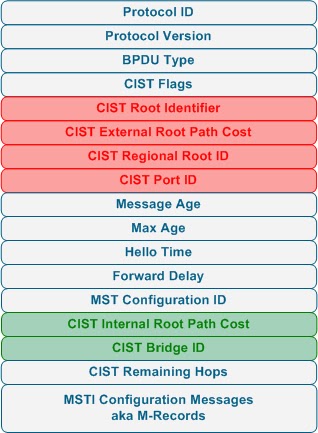
.Below is an MSTP bpdu.


Commands
spanning-tree mode mst - set mode to mst
spanning-tree mst configuration- enter mst config mode
name 'regionname' - set mst region name
revision 'revisionno' - set mst revision number
instance 'instanceid' vlan 'vlan range' - specify instance id and vlan range

spanning-tree vlan 'vlan id' root primary/secondary - set switch as root for vlan this a macro that checks current vlan root and decrements lower than it. It does not take account future switches coming on with lower priority. This commands works for 802.1d and 802.1w also.


Rapid Spanning Tree

  • came about as the delay of convergence for spanning-tree 802.1d was too slow for real time networks (taking 45secs to 1minute) to converge. With the advent of real time traffic like voip video over ip and delay sensitive traffic like citrix a faster solution was required.
  • The biggest difference is it is not timer based spanning-tree 802.1d used cautionary timers  like max age + forward delay of listening as a way of being sure that change had occured and to start to reconverge the spanning-tree this lead to slow down on spanning-tree convergence.
  • Switches in rspt generate bpdus to other neighboring switches as way of communcating rather than just the root bridge generating bpdu which was the case 802.1d   
  • RSTP use a synch process neighboring switches can agree very quickly on the status a design of the spanning-tree during initial setup and during spanning-tree changes making the convergence extremely quick
  • In order for this synch process to work out the port the switche need to know there ports are only connected to 1 neighboring switch so the ports must be full duplex and p2p
  • we have cut down state of discarding/learning and forwarding
  • we have more port roles with root designated edge and backup
  • root remains the same as always lowest cost to root bridge
  • alternative is the inbuilding of uplink fast it provides an alternate port to the root brige in case of root port failure
  • edge port inbuilding of port fast it for ports connecting to non switching devices configured the same as port fast
  • a backup port provides a back to designated port for the segment it is on.
  • When a switch detects a change it starts a tc timer (twice the hello time) + flushes it cam table while this timer is on it generates all bpdus out with tcn set bpdus. On reciept of tcn marked bpdu neighboring switches do the same so propgates through the spanning-tree very quickly.
  • RSTP is backward compatiable with 802.1d. When a switch recieves a 802.1 d bpdu it will wait twice the hello time and then fall back to compatablilty mode with 802.1d.
  • if you do sh spanning-tree vlan "vlanid" if you see p2pedge your connected to rstp switch if you see p2peer(stp) your connected to legacy spt device
Below is the RST BPDU FORMAT


Commands

config() spanning-tree mode rapid-pvst

FLEX LINKS

  • Define a backup link for a interface like an alternative for small scale enviorments to spanning-tree
  • Use thee mmu(mac address move) when switching to backup interface to spoof updates for all sources out new port inorder to get upstream switches to update there cam tables without causing flooding.
  • When you enable this backup link you disable stp on the primary and backup link
  • You have to enable mmu on all switches.


Configuration

int fa0/13
switchport backup interface fa0/17 mmu primary vlan 1

mmu is mac address move feature and the vlan is the vlan that the mmu data will be sent out
you also have to enable the mac address table move on all switches

mac-address-trable move update (recieve/transmit) so transmit on the switch with the backup interface and recived on the other switches

sh mac address-table move update

sh interface switchport backup

switchport backup interface fa0/17 premption mode force/bandwidth
also you may want to enable preemtion if the case your primary link comes backup to do
this in interface modeforce will always return to the primary specfied link bandwidth will preempt in the case that one link gets increase bandwidth

switchport backup interface fa0/17 premption delay 'in sec' to say how long it should wait to preempt

Friday, December 2, 2011

Spanning-Tree Tools


Port fast

  • Enters spanning tree forwarding state immediately
  • If recieves bpdu it loses it port status + transtions throught the spanning tree states
  • Must P2P and connected to non-switching device i.e a edge port
Commands

spanning-tree portfast default -  global command all non trunking ports will be portfast enabled

spanning-tree portfast - interface command individual switch them on with the command at interface level

spanning-tree portfast trunk -In general you would not use portfast on trunks but there is case where you may want for example you are connecting to vmware servers a trunk to vmares in the case we could put port fast on a trunk with the command


STP Uplink FAST

Uplink fast is basically a way of speeding up spanning tree convergence in the event of DIRECTLY connected root port having an issue. What it can do if it keeps track of it altenate ports to the root which are in the blocking state.In the event the root port goes down it can near on instantly switch to the alternate port and start forwarding rather then waiting for the blocking listen learning phases
  • Switch with uplink fast enabled should be transit switch to the root for other switches
  • To ensure this happens when enabled it sets it bridge priority to 49152 and port costs are increased by 3000
  • On switchover to alternative port the uplink switches need to update there cam to new port rather then sending a TCN notification and forcing a flush + delaying the failover the uplink switch spoofs all the sources in it cam table to make it look like all the sources are sending this update + sends the update out the new port upstream switches will update there cam table based on this update
  • When the primary link comes back availible uplink fast does not switchback straight away. It waits 2 times the forwarding delay + 5 seconds. The main reasons for this is that it is accounting for flaps on the primary link and also the primary link on the upstream switch will be transitionating through the spanning-tree states so if it switchover immediately it would be waiting for the upstream switch to complete its computation with dataplane forwarding  

Commands

spanning-tree uplink fast - to enable in global config mode

Backbone Fast

Backbone fast is technology in legacy spanning tree to detect an upstream issue. It is not for direct failures.

BackboneFast icheck if the root bridge is still alive using an algorith called RLQ. The process is simply put as the following:
the local switch sends a RLQ Request out its ports. Two figures can be distinguished:
  • local switch receives RLQ Reply on its current root port: everything is fine, Root Bridge is OK
  • local switch receives RLQ Reply on a non root port: there's a problem with the Root Bridge. The MaxAge timer expires immediately.
SO basically the 20 second max age delay is cut out in case of failure. It still has to go through the other port states listening and learning etc. So it is not feature for transparent failover but for a quicker convergence of spanning in case of upstream failure

Commands

spanning-tree backbonefast -on all switches. If not on all upstream switches it will not work as rlq reply would not be generated

STP BPDU Filter

Is used to filter bpdus on an interface. You may want to do this on access layer ports as security measure so to stop bpdu been generate out where potentially if a person was to get a connection to access layer port they could find information in regard to the current root bridge. It is like passive interface in routing protocols ospf eigrp
  • potential loop if connecting to switching device as your effectively disabling spanning tree
  • Enabled either globally or interface. Globally it is enabled on all portfast enabled ports.
  • Globally can be safer as if switching device is plugged and bpdu is recieved the port will lose it portfast status and in turn lose its bpduguard whereas if enabled on interface it will just ignore bpdus which could result in two ports on segment entering the forwarding state causing a potentiatl layer 2 loop

Commands

spanning-tree portfast bpdufilter defaultt- global command to enable on all portfast ports
spanning-tree bpdufilter enable- interface command to singular enabe on port

STP BPDU Guard

  • if a bpdu is recieved on bpdu guard port the bpdu port is err disabled
  • to renable a admin would need to do a shut no shut or set the err disable recovery timer.
  • this can also be enabled on interface or global.
  • interface over rides global
  • errror disables on both interface and global
Commands

spanning-tree portfast bpduguard default -  global command this will enable bpduguard on portfast ports

spanning-tree bpduguard enable- interface command

to enable an error disable timeout in global config

config() errdisable recoveryt cause bpduguard
config() errdisable recovery interval 30

Spanning Tree root Guard

  • root guard is a solution to block superior bpdu from influencing the root on certain ports. It is to stop an attmept hijack of the root or potential mistakenly connecting a switch which you would not like to come root which may have a lower priority configured for spanning tree.
  • You would enable this on downstream interfaces in the spanning tree
  • if a superior bpdu is recived on root guard enabled port it will errdisable the port
  •  Will autorecover once the superior bpdu is not being recieved anymore
Command

config-if) spanning-tree guard root

Thursday, December 1, 2011

Spanning Tree 802.1 D Root Bridge,Root Port Designated Port Elections


Spanning-Tree 8021d

Spanning-tree uses control configuration messages called bpdus to communicate Diagrammed below.


There are three types of BPDUs:
  • Configuration BPDU (CBPDU), used for Spanning Tree computation
  • Topology Change Notification (TCN) BPDU, used to announce changes in the network topology
  • Topology Change Notification Acknowledgment (TCA)
General Overview
  • A bridge sends a BPDU frame using the unique MAC address of the port itself as a source address, and a destination address of the STP multicast address 01:80:C2:00:00:00.
  • BPDUS are exchanged every 2 seconds
  • Root Bridge Election Lowest Bridge Priority + Mac
  • Priorties go in 4096 increments priorty values 0-64440 with default being  32768
  • All ports are designated on root bridge
  • Non root brige calculate lowest cost port to root brige if equal it is lowest neighbor bridge id lowst port number. The is known as root port
  • All other ports connected to switches are either put into designated or blocking.
  • There can be only one designated port per lan segment it is decided lowest cost to the root lowest brige id and lowest port number
  • Costs are based on bandwidth fast ethernet 19  1gig is 4 10g is 2
  • STP calculation is timer based max age 20 seconds (if bpdu missed how long it waits to flush) forward delay is 15 seconds (how long before transitions fro each state) 
  • States are listening,learning,forwarding and blocking
  • Bpdus are only sent by the root
  • STP Timers can only be adjusted on roots
  • TCN occurs when interface is placed in forwading or when interface in forwarding or learning goes to blocking
  • TCN do not contain exact change info it is just a way of notifying of change. When a switch recieves a TCN it lowers it mac address aging from default of 5 minutes to 15 seconds
  • spanning-tree type ieee
  • Design spanning-tree pre instalation to ensure that your desired links to not get blocked i.e fast links getting blocked because of root placement. Also considered that switches computate the best path to the root so the root switch should be a central switch to your network.

Good Commands

Sh spanning-tree 'vlan id'

sh spanning-tree summary

spanning-tree vlan (vlan id) hellow time 'timein seconds'

spanning-tree vlan vlan id forward-time 'time in seconds'

spanning-tree vlan vlan id max-age ' '